SOFTWARE ENGINEERING-1
Software Engineering – I
What
is Software?
Software is a collection of
• Instructions
(Computer programs) that when executed provide desired function and
performance.
• Data
structure that enable the programs to adequately (effectively) manipulate
information. And
• Documents
that describe the operation and use of the programs.
• Software
is a logical entity rather than a physical system element.
Software
Engineering
Definition
of Engineering
Application of science, tools and methods to find cost
effective solution to problems
Definition
of SOFTWARE ENGINEERING
Software engineering is a systematic approach to the
development, operation maintenance and requirements of the software.
1.
Software engineering is the application of science and
mathematics by which the capabilities of computer equipment’s are made useful
to man via computer program, procedures and associated documents.
2.
Software engineering is a set of 3 elements methods,
tool & procedure software engineering methods provides.
The technical – how tools for building a software it
includes project planning estimation of the project system and software
requirement analysis design of data structure
architecture & algorithms procedures.
Software engineering tool provides automated &
semi-automated support for methods. When tools are integrated so that the
support can be made for software development is called CASE (Computer Added
Software Engineering). CASE combine software, hardware & software
engineering database. Software engineering procedures define the sequence in
which methods will be applied.
Goal
of Software Engineering
Software engineering is driven by three major factors as
are follows.
• Cost
• Schedules
• Quality
Characteristics of the Software
Software is a logical rather than a physical system element
therefore software has characteristic that are different then hardware
component.
1.
Software is
developed or engineered it is not manufacture in the classical sense.
In both activities software development and hardware
manufacturing, high quality is achieved through good design, but the
manufacturing phase for hardware can introduce quality problems that are
nonexistence (or easily corrected) for software. Both activities depend on
people, but the relationship between people applied and work accomplished is
entirely different. Both activities require the construction of a product, but
the approaches are different.
2. Software does not wear out failure.
Above figure depicts failure rate as a function of time for hardware. The
relationship often called the “bathtub curve” indicates that hardware exhibits
relatively high failure rate early in its life. (This failures are often
attributable to design or manufacturing defects); defects are corrected and the
failure rate drops to a steady state level (hopefully quite low) for some
period of time. As time passes, however, the failure rate rises again as
hardware components suffer from the cumulative effects of dust, vibrations, abuse,
temperature extremes, etc. Stated simply, hardware begins to wear out. Figure B
– Idealized and actual failure curves


3.
for software As shown in figure (B), the failure rate
curve for software shows that, undiscovered defects will cause high failure
rates early in the life of a program. These are corrected (without introducing
other errors) and the curve flattens as shown in figure (B). Software doesn’t
wear out, but it does deteriorate. During the software life, it will undergo
change (maintenance). As changes are made, it is likely that some new defects
will introduced, causing the failure rate cure to spike. Before the curve can
return to the original steady-state failure rate, another change is requested,
causing the curve to spike again. Slowly, the minimum failure rate level begins
to rise the software is deteriorating due to change. Hardware component wears
out; it is replaced by a spare part. There are no software spare parts.
Every software failure indicates an error in design or in
the process through which design was translated into machine executable code.
Therefore, software maintenance involves considerably more complexity than
hardware maintenance.
4.Most software is custom built rather than being assembled from
existing components. Re usability is an important characteristic of high
quality software component. A software component should be designed and implemented
so that it can be reused in many different programs. Modern reusable components
encapsulate both data and the processing that is applied to the data, enabling
the software engineer to create new applications from reusable parts. For e.g.
today’s interactive interfaces are built using reusable components that enable
the creation of graphics windows, pull down menus and a wide variety of
interaction mechanisms. Software components are built using a programming
language that has a limited vocabulary. An explicitly defined grammar and
well-formed rules of syntax and semantics. At the lowest level, the language
mirrors the instruction set of the hardware. But Sometimes reusable components
does not fulfill the requirement there may be some changes we want but because
of its complexity of code means we have to understand the whole component for
making some changes to it , which is very complex task instead of this we can
create a custom component.
Software Applications
1)
System software
2)
Real-Time Software
3)
Business Software
4)
Engineering and scientific software
5)
Embedded Software
6)
Personal Computer Software
7)
Web-Applications
8)
Artificial intelligence software
System
Software
System software is a collection
of a program written to service other programs. Some system software (e.g.
Compilers, editors and file management utilities) processes complex; but
determinate information structures.
Other system applications (e.g. operating system
components, drivers, telecommunications processors).
Real
time Software
Programs that
monitor/analyze/control real world events as they occur are called real time
software.
Elements of real time software
includes
– Data
gathering components
– Analysis
components
– Control
/ output components
– Monitoring
components
A real time system must respond
within strict time constraints.
Real time system differs from
interactive or time sharing. The response time of an interactive system can
normally be exceeded without disastrous results. Eg. Weather forecasting s/w
Business
Software
Business information processing
is the largest single software application area. Discrete systems (e.g.
Payroll, accounts receivable/payable, inventory etc.) have evolved into
management information system (MIS) software that accesses one or more large
databases containing business information.
Applications in this area restructure existing data
in a way that facilitates business operations or management decision making. e.g.
Client/Server computing application.
Engineering
and Scientific Software
Engineering and scientific
software has been characterized by “number crunching” algorithms.
Application range from astronomy
to volcano logy, from automotive stress analysis to space shuttle orbital
dynamics and from molecular biology to automated manufacturing.
Eg. Weather Forecasting s/w,
Radar s/w, military s/w
Embedded
Software
Embedded software resides in RAM
and is used to control products and systems for the consumer and industrial
markets.
Embedded software can perform
very limited and esoteric functions (e.g. key pad control for microwave oven,
washing Machine, AC etc.) or provide significant function and control
capability.
(e.g. Digital functions in an
automobile such as fuel control, dashboard displays, braking system, etc.)
Personal
Computer Software
Word processing, spreadsheets,
computer graphics, multimedia, entertainment, database management, personal and
business financial applications and external network or database access are
some of the example of personal computer software.
Eg. Desktop Based Applications
(Word, Excel, power point, Photoshop etc.)
Web-Applications
The web pages retrieved by a
browser are software that incorporates executable instructions. In essence, the
network becomes a massive computer providing almost unlimited software
resources that can be accessed by anyone with a modem.
Eg. Websites
Artificial intelligence Software
Artificial intelligence software
makes used of non-numerical algorithms to solve complex problems that are not
amenable to computation or straight – forward analysis.
An active Artificial Intelligence
area is expert systems, also called knowledge based systems.
Other application area for AI
software is pattern recognition (image and voice) theorem proving and game
playing.
In recent years, new branch of AI is Artificial
neural networks has evolved. A neural network simulates the structure of brain
processes (the function of the biological neuron). Eg. Decision Making s/w
Software Myths
Management Myths:
1.
We already have a book that’s full of standards and
procedures for building software. Won’t that provide my people with everything
they need to know?
Reality: The book of standards
may very well exist, but is it used? Are software practitioners aware of its
existence? Does it reflect modern software engineering practice? Is it
complete? Is it streamlined to improve time to delivery while still maintaining
a focus on quality? In many cases, the answer to all of these questions is
“no.”
2.
If we get behind schedule, we can add more programmers
and catch up (sometimes called the Mongolian horde concept).
Reality: people who were working
must spend time educating the newcomers.
3.
My people have state-of-art software development tools;
after all, we buy them the newest computers.
Reality: It takes much more than
the latest model mainframe, workstation, or PC to do high-quality software
development. Computer-aided software engineering (CASE) tools are more
important than hardware for achieving good quality and productivity, yet the
majority of software developers still do not use them effectively.
4.
If I decide to outsource the software project to a
third party, I can just relax and let that firm build it.
Reality: If an organization does not understand how to
manage and control software projects internally, it will invariably struggle
when it outsources software projects.
Customer Myths:
1.
A general statement of objective is sufficient to begin
writing programs we can fill in the details later.Reality: poor up-front
definition is the major cause of failed software efforts.
2.
Project requirements continually change, but change can
be easily accommodated because software is flexible.
Reality: It is true that software
requirements change, but the impact of change project schedule and planning
will disturb
Practitioner’s
Myths:
1. Once
we write the program and get it to work, our job is done.
Reality: software can be expended
after it is delivered to the customer for the first time.
2. Until
I get the program “running” I have no way of assessing its quality.
Reality: One of the most
effective software quality assurance mechanisms can be applied from the
inception of a project—the formal technical review. Software reviews are a
“quality filter” that have been found to be more effective than testing for
finding certain classes of software defects.
3. The
only deliverable work product for a successful project is the working program.
Reality: A working program is
only one part of a software configuration that includes any elements.
Documentation provides a foundation for successful engineering and, more
important, guidance for software support.
4. Software
Engineering will make us to create voluminous and unnecessary documentation and
will invariably slow us down.
Reality: Software engineering is
not about creating documents. It is about creating quality. Better quality
leads to reduced rework. And reduced rework results in faster delivery times.
SOFTWARE
ENGINEERING LAYERS
Software
Engineering is the establishment and use of sound Engineering principles in
order to obtain economically software that is reliable and works efficiently on
real machines.
Software Engineering is around the
three layers (elements):
–
Process
–
Methods
–
Tools
–
Quality Focus
Process:
The foundation for software engineering is a process layer.
Software engineering process is the glue that holds the technology layers
together and enables rational, timely development of computer software.
Process defines a framework for a set of key process areas
that must be established for effective delivery of software engineering
technology.
The key process area forms the basis for management control
of software projects and establish the context in which technical methods are
applied, work products (models, documents, data, reports, forms, etc.) are
produced, milestones are established, quality is ensured, and change is
properly managed.
Process is a step by step plan to complete a task.
Methods:
SE methods provide the technical “how to’s” for building
software. Methods encompass a broad array of tasks that include requirements
analysis, design, program construction, testing and maintenance.
SE methods relay on a set of basic principles that govern
each area of the technology and include modeling activities and other
descriptive techniques.
Tools:
SE tools provide automated or semi-automated support for the
process and the methods.
When tools are integrated so that information created by one
tool can be used by another, a system for the support of software development,
called Computer Aided Software Engineering (CASE) is established.
CASE combines software, hardware and software engineering
database ( a repository containing important information about analysis,
design, program construction and testing) to create a software engineering
environment that is analogous to CAD/CAE (Computer Aided Design / Engineering )
for hardware.
Generic-View-of-Software-Engineering
The work that is associated with software engineering can be
categorized into three generic phases:
1.
Definition phase
2.
Development phase
3.
Maintenance phase
Definition Phase:
Definition phase answers “what” questions that is during the
definition the software developers attempts to identify.
• What
information is to be processed?
• What
function and performance are desired?
• What
validation conditions are required?
• What
types of interfaces are to be established?
• What
design constraints exists?
All the questions can be answered through
1.
System Analysis
2.
Software Project Planning
3.
Requirement Analysis
Development Phase:
Development phase answered “How” questions. In this phase
developer attempts to answer
• How
data structure and software architecture are to be designed?
• How
procedural details are to be implemented?
• How
design will be translated into a programming language? How
testing will be performed?
All the previous questions can be answered through
1.
Software Design
2.
Coding and
3.
Software Testing
Maintenance Phase:
The maintenance phases focus on change that is associated
with:
• Error
correction
• Adaptation
required
• Enhancement
• Prevention
Error
Correction
It is likely that the customer will uncover defects in the
software. Corrective maintenance changes the software to correct defects.
Adaptation
Over time, the original environment (e.g. CPU, OS, Business
Rules etc.) for which the software was developed is likely to change. Adaptive
maintenance results in modification to the software to accommodate changes to
its external environment.
Enhancement
As software is used, the customer/user will recognize
additional functions that will provide benefit. Perfective maintenance extends
the software beyond its original functional requirements.
Prevention
Computer software deteriorates due to change, and because of
this, preventive maintenance often called software re engineering must be
conducted to enable the software to serve the needs of its end users.
What are umbrella activities in software engineering?
The phases and related steps
described in generic view of SE are complemented by a number of Umbrella
Activities as under:
1.
Software project tracking and control
Allows the team to assess progress
against the project plan and take necessary action to maintain schedule.
2.
Formal technical reviews
Uncover
and remove errors before they propagate to the next action.
3.
Software quality assurance
Defines and conducts the activities
required to ensure software quality.
4.
Software Configuration management
Manages the effect of change
throughout the S/W process
5.
Document preparation and production
Encompasses [include] the activities
required to create work products such as models, documents, etc.
6.
Re usability management
Defines criteria for work product
reuse.
7.
Measurement
Defines and collects process,
project, and product measures that assist the team in delivering S/W that meets
customers’ needs.
8.
Risk management
Assesses the risks that may
affect the outcome of the project or the quality.
Umbrella activities are
applied throughout the software process.
Linear sequential
model or Classic life cycle model or Waterfall model The simplest process
model is the water fall model which states that the force is organized in a
linear order. So it is also known as the linear sequential model or classic
life style model. The linear sequential model is oldest and the most widely
used paradigm for software engineering. Linear sequential model suggests a
systematic, sequential approach to software development that begins at the
system level and progresses through analysis, design, coding, testing and
maintenance.
Fourth Generation Techniques (4GT)
“Fourth generation techniques are the
package of software tools that enable a software Engineer to specify the
characteristics at a high level and then a source code is automatically
generated based on these specifications” In 4GT, we can specify the user
requirements in graphic notation or small abbreviated Language form.
The 4GT includes following tools:
§
Data definition
§
Data manipulation
§
Non procedural language for query
§
Report generation
§
Code generation
§
Spreadsheet capability
Four steps for making a software product using 4GT:
§
Requirement gathering
§
Design strategy
§
Implementation
§
Transformation into product
Advantages of 4GT:
§
Reduction in software development time.
§
Improved productivity of software engineers.
§
4GT helped by CASE, tools and code generators
that offer solution to many problems.
Disadvantages:
§
Some 4GT are not at all easier than programming
languages. Generated source code are sometimes
inefficient´
§
Time is reduced for only small and medium
projects.
§
Large software developed by 4GT is not
maintainable or difficult to maintain.
Effort Distribution
Each of the software project estimation techniques required
to complete software development.
A recommended distribution of effort across the definition
and development phases is often referred to as the 40–20–40 rule. Forty percent
of all effort is allocated to front-end analysis and design. A similar
percentage is applied to back-end testing. You can correctly infer that coding
(20 percent of effort) is de-emphasized. 40%
– analysis and design
20% – Coding
40% – Testing
Requirement Analysis and Testing is the main Part of
Software development. Coding is not most expensive
In-general Ration
10-25 % – Requirement
Analysis
20-25 % -Design
15-20% -Coding
30-40% -Testing
Systems analyst
A systems analyst is a person
who uses analysis and design techniques to solve business problems using
information technology. Systems analysts may serve as change agents who
identify the organizational improvements needed, design systems to implement those
changes, and train and motivate others to use the systems.
A systems analyst may:
• Identify,
understand and plan for organizational and human impacts of planned systems,
and ensure that new technical requirements are properly integrated with
existing processes and skill sets.
• Plan
a system flow from the ground up.
• Interact
with internal users and customers to learn and document requirements that are
then used to produce business requirements documents.
• Write
technical requirements from a critical phase.
• Interact
with designers to understand software limitations.
• Help
programmers during system development, e.g. provide use cases, flowchartsor
even database design.
• Perform
system testing.
• Deploy
the completed system.
• Document
requirements or contribute to user manuals.
• Whenever
a development process is conducted, the system analyst is responsible for
designing components and providing that information to the developer.
Requirement Analysis

• Requirements
analysis is a software engineering task that bridges the gap between system
level software allocation and software design.
• It
enables the system engineer to specify software function and performance
indicate software’s interface with other system elements and establish
constraints that software must meet.
• Requirement
analysis allows the software engineer (i.e. analyst) to refine the software
allocation and build models of the data, functional and behavior domains that
will be treated by software.
Finally, the requirement specification provides the
developer and the customer with the means to assess quality once software is
built.
Requirement analysis divided into five
areas:
1)
Problem recognition
2)
Evaluation and synthesis
3)
Modeling
4)
Specification
5)
Review
Requirement analysis Task
1).
Problem Recognition
Initialize the system analyst studies the system
specification of the software and project plan and the analyst must establish
contact with management and technical staff of the user or customer
organization and software development organization. The project manager can
serve as a coordinator for establishment of communications paths. The goal of
the analysis is to reorganization the basic problem element which is perceived
by the user or customer.
2).
Synthesis and evaluation
Problem evaluation and solution synthesis is the next major
area of effort for analysis. The analyst
must evaluate the flow and content of information, define and expand all
software function, understand software behavior in the context of event of the
effect system, establish system interface characteristics and on cover design
constrains. Each of these tasks serves to describe the problem so that and
overall approach or solution may be synthesis. Evaluating current problems and desired information and input
and the output the analyst begins to synthesis one or more solution.
Throughout evaluation and solution synthesis the analyst’s
primary focus of analyst is on “What” or “How” what data does the system
produce and consume what functions must the system perform what interfaces are
define and what constrains applied.
3).
Modeling
During the evaluation and
solution synthesis activities the analyst creates models of the system in an
effort to better understand data and control flow, functions processing and
behavior operation. The model serves the foundation for software design and the
basic for the creation of a specification for the software.
4).
Requirement Specification & Review:
After making the model analyst makes a plan and schedule for
development. The information gathered during the system study was analyzed to
determine the requirement specifications. Based on the issues governing the
system, requirements in non-technical terms formulated.
1.
We need to develop rough prototype to check the basic
functionality of the software.
2.
If the major modules are not working properly then the
software might not satisfy the user.
3.
Interaction between the operator and system analyst
must be fast and reliable.
Requirement Gathering Techniques (Elicitation):
–
1. Initiating a Process of Requirement
Gathering: –
1.
The most commonly used requirement gathering technique
is to conduct a meeting or interview.
2.
We can say to get the requirements of our customer
communication must be initiated.
3.
The analyst start by asking context free questions i.e.
a set of questions that will lead to a basic understanding of the problem.
4.
Analyst and customer arrange one meeting, in that
meeting customer gives the software requirement, based on that requirement
analyst asks some question to customer for better understanding the requirement
and overall goals and the benefits e.g. the analyst can ask following
questions.
• Who
is behind the request for this system?
• Who
will use the solution?
• What
will be the economic benefit of a successful solution?
• Is
there another source for the solution that customer require?
The next set of questions enables the analyst to gain better
understanding of the problem and the customer to voice about the solution. The
second set of questions can be how can
you characterize good output that would be generated by a successful
solution of software.
• What
problems will this solution address?
• Can
you describe the environment in which the solution will be used?
• Will
special performance issues or constraints affect to way the solution approach?
• The
final set of questions focuses on the effectiveness of the meeting, it is
called Meta
• Can
anyone else provide additional information?
• Should
I ask anything else about the problem?
• Are
my questions relevant to the problem that customer have? Am I asking
too many questions?
2. FAST
(Facilitated Application Specification Technique): –
• In
this technique or approach joint team of
customers & developers who work together to identify the problem,
purpose and elements of the solution.
• In
that team one expert from each field included like Analyst side(one expert from
developers side , one from tester side , one from designer side etc.) same way
the experts from the customer side from each department are included in the
meeting.
• Each
experts note-own some points in meting
based on points they prepares one report and finally reports are submitted to
leader of the team.
• After
collecting the all the reports from the experts analyst or (team leader) will
prepares an agenda for software development means make schedule.
• FAST
has been used predominantly by the information system but the technique affects
quotient for improved communication in applications of all kinds. The basic
guidelines for FAST approach are,
1)
Meeting is conducted and attempted by both software
engineers and customers.
2)
Rules for preparation and participation are
established.
3)
An agenda is suggested that is formal enough to cover
all important points.
4)
Facilitate controls the meeting.
5)
Definition mechanism is used it when it can be a
worksheet or an electronic bulletin board.
6)
The goal is to identify the problem, proposed elements
of the solution, negotiate different approaches and specify a preliminary set
of solution requirements.
§ Initial
meetings between the developer and customer occur and basic questions and
answers help to establish the scope of the problem and the overall perception
of the solution
§ Out
of these initial meetings the developer and customer write one or two page
product request. Meeting place, time and date for FAST are selected and a
facilitator is chosen.
§ Attendees
from both the development and customer organization are invited to attempt. The
product request is distributed to all attendees before the meeting date while
reviewing the request in the days before the meeting each FAST attendees is use
to make the list of objects that are part of the environment surrounds the
system, other objects that are to be produced by the systems and objects that
are used by the system. To perform its function list of constraints i.e. cost
size and sometimes business rule of policy, performance criteria are also
developed.
§ Each
person on the FAST team develop the list which is describe about objects
describes for e.g. safe home system might include smoke detectors, window &
doors sensor, motion detector and alarm, an event from which a sensor has been
activated, a control panel and so on.
§ Services
can be setting the alarm, monitoring the sensor dialing the phone, reading
display.
§ In
a similar fashion each FAST develop list of constraints as a FAST meeting being
the first topic of discussion is the need and justification for the new product
at the FAST.
§ After
the mini specifications are computed each FAST attendees makes a list of
validation criteria for the product or system.
§ Finally
one or more participants is assigned the task of writing the complete
specification using all inputs from the FAST meeting and later on all
requirement point of view from all members and refinement is prepared for
development of a design.
3. QFD
(quality Function Deployment): –
QFD is a quality management
technique that translates the need of the customer into technical requirement
for software. QFD defines requirement in a way that maximizes the customer
specification. QFD constraint on maximizing customer satisfaction from the software
engineering process. QFD identifies three types of requirements. (1) Normal
Requirements, (2) Expected Requirements and (3) Exciting Requirements.
1.
Normal Requirements:–
The objectives and goals that are defined a product or
system during meetings with the customer if these requirements are presents
then the customer is satisfied. Examples of normal requirements might be
requested types of graphical display, specific system functions and define
level of performance.
2.
Expected Requirements:–
These requirements are
implicit to the product or system and may be so fundamental that the customer
does not explicit state them their absence then it is a cause of significant
dissatisfaction examples of expected requirements are base of human machine interaction,
overall operational correctness and reliability and software installation.
3.
Exciting Requirements:–
These features go beyond the
customers expectation proves to be very satisfying when present. E.g. word
processing software is requested with standard function, the delivered product
contains a number of page layout capabilities.
In meeting with the customer
function deployment is used to determine the value of each function i.e.
required for the system information deployment identities both the data objects
& events that the system must consume and produced. Task deployment
examines the behavior of the system or product within the given
environment.
QFD uses customer interviews
and observation surveys and examination of historical data as row data for the
requirement gathering activity. Those data are then translated into a table of
requirement and this table is called customer voice table.
Analysis Principles:
1.
The information domain of a problem must be represented
and understood.
2.
The functions that the software is to perform must be
defined.
3.
The behavior of the software (as a consequence of
external events) must be represented.
4.
The models that depict information function and
behavior must be partitioned in a manner and uncovers details in a layered (or
hierarchical) fashion.
5.
The analysis should move from essential information
toward implementation detail.
The information domain is examined so that function may be
understood completely.
The models are used so that the
characteristic of function and behavior can be communicated in a compact
fashion. Partitioning is applied to reduce complexity.
1.
Understand the problem before you begin to create the
analysis model.
2.
Develop prototypes that enable a user to understand how
human/machine interaction will occur.
3.
Record the origin of and reason for every requirement.
4.
Use multiple views of requirements
5.
Rank requirements
6.
Work to eliminate ambiguity
A software engineer who takes
these principles to heart is more likely to develop a software specification
that will provide an excellent foundation for design.
The Information Domain:
All software applications can
be collectively called data processing. Software is built to process data also
processes the events. An event represents some aspect of system control and is
really nothing more than Boolean data.
e.g. software controlled automobile
engine.
(i.e. to control flow of fuel)
The information domain contains
three views of the data and control as each is processed by a computer program.
The views are as:
1.
Information Flow
2.
Information content and relationship
3.
Information structure

1). Information flow
The information flow
represents the manner in which data and control change as each moves through a
system.
The information applied to the
data are function or sub-functions that a program must perform.
Data and control that move
between two transformations (functions) define the interface for each function.
2)
Information Content and
Relationship
Information content represents
the individual data and control objects that comprise some larger collection of
information that is transformed by the software.
e.g. The data object paycheque
is a composite of a number of important pieces of data.
The content of paycheque is
defined by the attributes that are needed to create it. Similarly, the content
of a control object called system status, might be defined by a string of bits.
Each bit represents a separate item of information that indicates whether or
not a particular device is on or off-line.
Data and control objects can be
related to other data and control objects.
e.g. The data object paycheck
has one or more relationship with the objects timecard, employee, bank and
others. During the analysis of the information domain, these relationships
should be defined.
3)
Information Structure
Information on structure represents
the internal organization of various data and control items.
A concept of data structure
refers to the design and implementation of information structure.
Questions like,
• Are
data and control items to be organized as an n-dimensional tables OR
Hierarchical tree structure?
• Within
the context of the structure, what information is related to other information?
• Is
all information contained within a single structure or are distinct structures
to be used?
• How
does information structure relate to information in another structure?
Are answered by an assessment
of information structure.
Specification:
The specification is directly
associated with the quality of software. If the specification is incomplete its
results into frustration and confusion among the software engineer and
ultimately it affects the quality, completeness, timeliness of the software.
The software specification can
be viewed as representation of the requirements which tends us to successful
software implementation.
Specification is a description
of what is desired rather than how it is to be obtained.
Specification Principles
A number of specification
principles adapted from the work of Balzer and Goldman [BAL86]:
1)
Separate functionality from implementation
2)
Develop a model of the desired behavior of a system
that encompasses data and the functional responses of a system to various
stimuli from the environment.
3)
Establish the contact in which software operates by
specifying the manner in which other system components interact with software.
4)
A specification must encompass the environment in which
the system operates.
5)
A system specification must be a cognitive model
6)
A specification must be operational
7)
A specification must be tolerant of incompleteness and
augmentable.
8)
A specification must be localized and loosely coupled.
The list of basic specification
principles noted above provides a basis for representing software requirements.
Representation of Specification
A set of guidelines for
represents the specification is as under.
1) Representation format and content should be
relevant to the problem. i.e. a specification of a manufacturing automation
system would use different symbology, diagrams and language than the
specification for a programming language compiler.
2) Information contained within the
specification should be nested.
Representation should reveal
layers of information so that a reader can move to the level of detail that is
required. Paragraph and diagram numbering schemes should indicate the level of
detail that is being presented.
3) Diagrams and other notational forms should
be restricted in number and consistent in use.
Confusing notation or
inconsistent notation (graphical or symbolic) degrades understanding and tends
towards errors.
4) Representation should be revisable.
Software/System Requirement Specification
Software requirement
specification (SRS) is produced at the end of analysis task. The following is
the general outlines for SRS, which is suggested by National Bureau of
Standards and U.S. Departments of defense.
1.
Introduction
2.
System reference
3.
Overall description
4.
Software project constraints
5.
Information Description
6.
Information content representation
7.
Information flow representation
8.
Data flow
9.
Control flow
III. Functional Description
1.
Functional partitioning
2.
Functional Description
3.
Processing narrative
4.
Restrictions / Limitations
5.
Performance requirements
6.
Design constraints
7.
Supporting diagrams
8.
Behavioral Description
9.
System states
10.
Events and actions
11.
Validation criteria
12.
Performance bounds
13.
Classes of tests
14.
Expected software response
15.
Special considerations
16.
Bibliography
VII. Appendix
The Introduction
states the goals and objectives of the software, describing it in the context
of the computer based system.
The Information
Description provides a detailed description of the problem that software
must solve.
A description of each function
required to solve the problem is presented in the Functional Description. A processing narrative is provided for each
function; design constraints are stated and justified; performance characteristics
are stated. The Behavioral Description
section examines the operation of the software as a consequence of external
events and internally generated control characteristics.
The most important section of SRS is Validation Criteria.
The Bibliography
contains references to all documents that relate to the software. These include
other software engineering documentation, technical references, vendor
literature, and standards.
The Appendix
contains information that supplements the specification. Tabular data, detailed
description of algorithms, charts, graphs, and other material are presented as
appendixes.
In many cases SRS may be
accompanied by an executable prototype, paper prototype, or preliminary user’s
manual.
The preliminary user’s manual
presents the software as a black box. That is, heavy emphasis is placed on user
input and resultant output. The manual can serve as a valuable tool for
uncovering problems at the human-machine interface.
Characteristics of SRS:
(System Requirement Specification Document)
The final output of the
requirement analysis phase is the software requirements specification document
it is also known as SRS document. To properly satisfy the basic goals and SRS
should contain different types of the requirements following are some of the
desirable characteristics of SRS.
1).
Correct
An SRS is correct if every
requirement included in the SRS represents something required in the final
system.
2).
Complete
An SRS is complete if every
this software is supposed to do the responses of the software to all classes of
input data are specified data into SRS. Correctness ensure that what is
specified is done correctly, completeness ensures that everything is indeed
specified.
3).
Unambiguous (unmistakable/clear cut)
An SRS is unambiguous if and
only is every requirements stated or written has one and only one
interpretation.
4).
Verifiable
Verification of requirements
is done through reviews. It also implies that an SRS is understandable at least
by the developer, by client and by the user.
5).
Consistent
An SRS is consistent if there
is no requirement that conflict with another terminology can cause
inconsistency. Ex Different requirements may use different terms to refer to
the same object. There may be logical conflict may be requirement causing
inconsistency. Ex A requirements states that an event E should occur before F
but than other set of requirement stays that and event F should occur before
event E. Inconsistency in SRS can be a reflection of major problem.
6).
Ranked of importance / Stability
An SRS is ranked for an
importance if for each requirement the importance and stability of a
requirement reflect a term of expected change stability of a requirement
reflects in futures. Writing and SRS is an interactive process, when the
requirement systems are specified.
7).
Modifiable
They are later modified as the
needs of the clients change. SRS should be easy to modify. SRS is modifiable if
its structures and style are such that any necessary change can be made easily
while continuing completeness and consistency.
8).
Traceable
An SRS is traceable if the
origin of each of its requirement is clear and if it fulfill the reference in
of each requirement in future development should be traceable to some design
and code element and backward traceability requirement. If be possible to trace
design and code element to the requirement. They support traceability aids
verification and validation from all this characteristics completeness is the
most important requirement. One of the most common problems in requirement
specification is when some of the requirement of the client is to specify.
Components of SRS:
Some of the system properties
that an SRS should specified and the basic an SRS must address are as follows.
1.
Functionality
2.
Performance
3.
Design Constrains imposed on an implementation
4.
External Interfaces
1). Functionality
Specified which output should
be produce from the given input. They describe the relationship into the input
or output of the system for each functional requirement for detail description
is all the data input and their source the unit of measure and the range of
valid output must be
Specified all the option to be
performed on the input data to obtain the output should be specified. This
include specified the validity checks on the input or output data parameters
effected by the option and equations or other logical there must be used to
transform, the input or the corresponding output.EX if there is a formula
keep must be specified in SRS. An important part of the specification is the
system behavior in abnormal situation like invalid input or error during
computation. The function requirement must clearly state that what the system
should the who keep such situation occurs specified the behavior of the system
for invalid input invalid output. Ex of the situation is an airline reservation
system where a reservation cannot be made even for valid passenger if the
airline is fully full in sort the system behavior for input or all possible
stacks should be specified.
if there is a formula
keep must be specified in SRS. An important part of the specification is the
system behavior in abnormal situation like invalid input or error during
computation. The function requirement must clearly state that what the system
should the who keep such situation occurs specified the behavior of the system
for invalid input invalid output. Ex of the situation is an airline reservation
system where a reservation cannot be made even for valid passenger if the
airline is fully full in sort the system behavior for input or all possible
stacks should be specified.
2). Performance Requirement
This part of an SRS specified
the performance constraints on the software system. The entire requirement
relating to the performance characteristics of the system must be clearly
specified there are two types of performance requirements.
1. Static
2. Dynamic
1. Static Requirement
Static requirement are those
that do not imposed constraints on the execution characteristics of the system.
This includes requirement like the number of terminal to be supported the
number of simultaneous users to be supported and the number of files that the
system has to process and their sizes. These are also called capacity
requirement of the system.
2. Dynamic Requirement
Dynamic requirement
specification constraints on the execution behavior of the system this includes
response and through put constrains on the system. Response time is expected
time for the compilation on an option and through put is an expected time for
the compilation on an option and through put is an expected number of options
that can be perform in a unit time. The SRS may specify. The number of
transaction must be process for time. What the response time for a particular
command should be requirement such as response time should be good or the
system must be able to process all the transaction quickly are not describe
because they are depended on machine can verified according to the machine.
3). Design constraints:
There are number of factors in
client environment that may restrict that choice of a designer such factors is:
1.
Resource limits
2.
Operating Environment
3.
Reliability & Fault tolerance
4.
Security environment
and Policies of organization
1. Resource Limits
Standard Compliance
This specifies the
requirements for be standard that the system must follow the standard may
include the report format and accounting procedure.
2. Operating Environment
Hardware Limitations
The software may have to
operate on some existing or predetermine hardware. Hardware limitations can
include the types of machines; operating system available on the system
languages supported a limit on primary and secondary storage.
3. Reliability and fault tolerance
Fault tolerance requirement can
place a major constraints on how the system is to be design fault tolerance
requirement often make the system more complex and expensive requirement it
recovery require are integral part of the system. Detailing what the system
should do if some failure occurs to ensure certain properties reliability is
very important for critical applications.
5.
Security
Security requirements are particularly significant in
defiance system an many database system security requirements place
restrictions on the use of certain commands, control access to data , provide
different kinds of access requirement for different people, require the use of passwords and cryptography
techniques and maintain a log of activities in the system.
4). External Interface Requirements
All the possible interaction of
the software with people, hardware and other software should be clearly specify
for the user interface the characteristics each user interface of the software
product should be specify user interface is become an important and must be
given proper attention a preliminary user manual should be created with all
user commands, screen formats, an explanation of how the system will appear to
the user and feedback and error messages for hardware interface requirement the
SRS should specified the logical characteristics of each interface between the
software product and hardware components if the software is to execute on
existing hardware or on predetermine hardware all the characteristics of the
hardware including memory restriction should be specified. The interface
requirement should specify the interface with other software the system will
use or that will use the system. These include the interface with the operating
system and other applications.
Specification Review:
Review of SRS is conducted by
both software developer and customer.
The review is first conducted
at a macroscopic level. At this level, reviewers attempt to ensure that the
specification is complete, consistent, and accurate.
The following questions are
addressed:
1)
Do stated goals and objectives for software remain
consistent with system goals and objectives?
2)
Have important interfaces to all system elements been
described?
3)
Is information flow and structure adequately defined
for the problem domain?
4)
Are diagrams clear? Can each stand-alone without
supplementary text?
5)
Do major functions remain within scope, and has each
been adequately described?
6)
Is the behavior of the software consistent with the
information it must process and the function it must perform?
7)
Are design constraints realistic?
8)
Have the technological risks of development been
considered?
9)
Have alternative software requirements been considered
10)
Have validation criteria been stated in detail? Are
they adequate to describe a successful system?
11)
Do inconsistencies, omissions, or redundancy exits 12)
Is the customer contact complete?
13)
Has the user reviewed the preliminary user’s manual or
prototype?
14) How
are planning estimates affected?
Coupling and Cohesion
When a software program is
modularised, its tasks are divided into several modules based on some
characteristics. As we know, modules are set of instructions put together in
order to achieve some tasks. They are though, considered as single entity but
may refer to each other to work together. There are measures by which the
quality of a design of modules and their interaction among them can be
measured. These measures are called coupling and cohesion.
• Cohesion
Cohesion is a measure that
defines the degree of intra-dependability within elements of a module. The
greater the cohesion, the better is the program design.

There are seven types of
cohesion, namely –
• Co-incidental cohesion – It is
unplanned and random cohesion, which might be the result of breaking the
program into smaller modules for the sake of modularization. Because it is
unplanned, it may serve confusion to the programmers and is generally
not-accepted.
• Logical cohesion – When logically
categorized elements are put together into a module, it is called logical
cohesion.
• Temporal Cohesion – When elements of
module are organized such that they are processed at a similar point in time,
it is called temporal cohesion.
• Procedural cohesion – When elements of
module are grouped together, which are executed sequentially in order to
perform a task, it is called procedural cohesion.
• Communicational cohesion – When
elements of module are grouped together, which are executed sequentially and
work on same data (information), it is called communicational cohesion.
• Sequential cohesion – When elements of
module are grouped because the output of one element serves as input to another
and so on, it is called sequential cohesion.
• Functional cohesion – It is considered
to be the highest degree of cohesion, and it is highly expected. Elements of
module in functional cohesion are grouped because they all contribute to a
single well-defined function. It can also be reused.
Coupling
Coupling is a measure that
defines the level of inter-dependability among modules of a program. It tells
at what level the modules interfere and interact with each other. The lower the
coupling, the better the program.

High coupling makes modifying
parts of the system difficult, e.g., modifying a component affects all the
components to which the component is connected.
Coupling is a measure
of interconnection among modules in a software structure. Coupling depends on
the interface complexity between modules. The point at which entry or
references made to a module and what data passes across the interface. In
software design we should try for lowest possible coupling.
• If
modules share common data, it should be minimized
• Few
parameters should be passed between modules in procedure calls
[recommended 2 – 4 parameters ]
Types of coupling, from strongly coupled (least desirable) Weakly
coupled (most desirable):
1)
Content coupling
2)
Common coupling
3)
External coupling
4)
Control coupling
5)
Stamp coupling
6)
Data coupling
There are five levels of
coupling, namely –
• Content coupling – When a module can
directly access or modify or refer to the content of another module, it is
called content level coupling.
• module
directly affects the working of another module
• occurs
when a module changes another module’s data or when control is passed from 1
module to the middle of another (as in a jump)
• Common coupling- When multiple modules
have read and write access to some global data, it is called common or global
coupling.
• 2
modules have shared data
• occurs
when a number of modules reference a global data area Eg.
In our Example Module c,g,k.
• Control coupling- Two modules are
called control-coupled0 if one of them decides the function of the other module
or changes its flow of execution.
• Stamp coupling- When multiple modules
share common data structure and work on different part of it, it is called
stamp coupling.
• Occurs
when complete data structures are passed from 1 module to another
• The
precise format of the data structures is a common property of those modulesEg.
In our Example between Module a and b.0
• Data coupling- Data coupling is when
two modules interact with each other by means of passing data (as parameter).
If a module passes data structure as parameter, then the receiving module
should use all its components.
• Only
simple data is passed between modules
• 1
to 1 correspondence of items exists
• Eg.
In our Example between Module a and c.
Design
Principles
Software design is both a
process and a model. The design process is sequence of steps that enable the
designer to describe all aspects of the software to be built. It is important
that the design process is not simply sequential process but it is a sense of
what makes quality software. The design model is the equi0valent of an
architectural plan for a house. It begins by representing the total things to
be built. Davis has suggested following principles for software.0
1.
The design
process should not suffer from “tunnel vision”means a good designer should
consider alternative approaches, judging each based on the problem, the
resources available to do the job and should consider all design concepts.
2.
The design
should be traceable to the analysis model means a single element of the
design model often traces to multiple requirements so it is necessary to have a
means for tracking how requirements have been satisfied by the design model.
3.
The design
should not reinvent the wheel means systems are constructed using a set of
design patterns. These patterns should always been chosen as an alternative to
reinvention because time is short and resources are limited so design time
should be invested in representing truly new ideas and integrating those
patterns that already exists.
4.
The design
should minimize the intellectual distance between the software and the problem
as it exists in the real word.
5.
The design
should exhibit uniformly and integration.Design is uniform means it appears
that one person develop the entire thing. Rules of style and formats should be
defined for a design till before design work begins. Design is integrated if
care is taken in defining interface between design components.
6.
The design
should be structured to accommodate change means if we are using
prototyping according to above concept.
7.
The design is
not a coding and coding is not a design means even when detail procedural
design are created for program components the level of abstraction of the
design model is higher than source code.
8.
The design
should be received and assess for quality as it is being created. A variety
of design concepts and design measures are available to access the designer is
assessing quality.
When these design principles
are properly applied the software engineer creates a design that exhibit both
external and internal quality factors. External quality factors are those
properties of the software that can be observed by users. E.g. speed,
reliability, concentrate etc. an inter quality factors are of important to
software engineer they lead to a high quality design from the technical point
of view to achieve internal quality factors. The designer must understand basic
design concepts.
Design
Concepts:
Following are some design
concepts which designer should keep in mind while preparing a design for the
software.
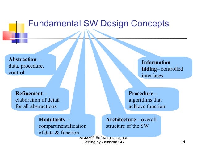
1.
Abstraction:–
Concentrate on the essential
features and ignore details that are not relevant Means hiding the complexity.
1)
Procedural
Abstraction: –
It is name sequence of
instructions that has a specific and limited function. E.g. procedural
abstraction would be the word open for a door for open implies a long sequence
of procedural steps like walk to the door, reached out and knocked and pull
door and step away from moving door etc.
Means in-sort hiding the
Procedure details here hiding the procedure of how to open door.
2)
Data
Abstraction: –
Data abstraction is a name collection of data that describes
a data object in the context of the procedural abstraction open we can define a
data abstraction called door like any data object. The data abstraction for
door would be a set of attributes that describe the door. E.g. Door type, swing
direction, opening mechanism, weight dimension etc. it follows that the
procedural abstraction would make use of information contain in the attributes
of the data abstraction door.
Means in-sort hiding the data
details here hide the door details.
3)
Control
abstraction:
Implies a program control
mechanisms without specify internal details.
Means in-short hiding the Control Details.
2.
Refinements: –
The process of program
refinement (modification or enhancement) is a partitioning process i.e. used
during requirement analysis. Refinement is actually a process of elaboration
(expansion). We begin with a statement of function or description of information
i.e. defines a high level of abstraction. The statement describes function or
information conceptually but provides no information about the internal working
of the functions or the internal structure of the information. Refinement
causes the system designer to elaborate on the original statement providing
more and more detail as each successive refinement occurs.
Abstraction and refinement are
complimentary concepts. Abstractions enable a designer to specify procedure and
data refinement helps the designer a detail at a low level.
3.
Modularity: –
Software is divided
into separately named and addressable components which are called modules.
Those are integrated to satisfy problem requirements. Modularity is a single
attribute of software that allows a program to be intellectually manageable.
Monolithic software i.e. a large program composed of a single module cannot be
easily readable the number of control paths, spend of referential number of
variables and overall complexity would make understanding close of impossible.

It is easier to solve a
complex problem when you break it into manageable pieces (Modules). When we
divide software in to modules then development effort also decreased. From
above graph we can show that as the number of modules grows the effort or cost
associated with integrating the module also grows. These characteristics leads
to a total cost or effort which shown in above figure. This is a M of modules
that would result in minimum development cost and here another important
question arises when modularity is consider how do we define an appropriate
module of a given size? The answer lies in the method use to define modules
within a system. These are arteries define that enable us to evaluate a design
method with respect to define an effective module system.
1)
Modular
Decomposability: –
Provide a systematic approach
for decomposing the problem into sub-problems. If a design method provides a
systematic mechanism for decomposable problem into the sub problem then we can
reduce the complexity of overall problem by achieving effective modularity
software.
2)
Modular
Composability: –
Modular Composability means if
a design method enable existing or reusable design components to be assembled
into a new system then the modular solution does not reinventing wheel.
3)
Modular
Understandability: –
If a module can be understood
as a standalone unit without reference to other module then it will be easier
to build and easier to change.
4)
Modular
Continuity: –
If small changes to the system
requirements results in changes to individual modules rather-then system wise
changes the impact of change all other side effects should be minimized.
5)
Modular
Protection: –
If any unexpected condition
occurs within a module and its effects are contain within that module only, the
impact of other side effects should be minimized.
4.
Software
Architecture: –
Architecture is the
hierarchical structure of program components or modules. There are some set of
properties that should be specified as an architectural design.
1)
Structural
Properties: –
This aspect of the architectural design represents the
components of a system.
2)
Extra
Functional Properties: –
The architectural design
description should address how the design architecture achieves requirements
for performance, capacity, security and other system characteristics.
The architectural design can be
represented using one or more different models.
1. Structural
Model: –
Which is represent
architectural as an organized collection of program components.
1. Framework
Model: –
Increase the level of design
abstraction by attempting to identify repeatable architectural design frame
works.
iii. Dynamic
Model: –
Address the behavioral aspects
of the program architecture it indicates how the structure or system
configuration may change as a function of external events.
1. Process
Model: –
Focus on the design of the
business or technical process that system must accommodate.
1. Functional
Model: –
It can be used to represent the
functional hierarchy of the system.
Control Hierarchy: –

The control hierarchy
also called program structure represents the organization of program
components and implies a hierarchy of control. It does not represent procedural
aspects of software such as sequence of software, occurrence, and order of
decision or representation of operations.
In above figure depth
and width provide an indication of the number of levels of control and
overall span of control. Fan – out
is a measure of the number of modules that are directly controlled by another
module. Fan – in indicate how many
modules directly control a given module? The control relationship among modules
is expressed in the following way. A
module that controls another module is said to be super ordinate to it and
a module controlled by another is said
to subordinate to the controller. In above figure module M is superordinate to modules a, b and c and module k is subordinate to module c.
Structural
Partitioning: –
Program
structure can be partitioned both horizontally and vertically. Horizontal partitioning: defines
separate principles branches of modular hierarchy for each major program
function. Control modules represents each coordination between remaining
modules and execution of the function, partitioning horizontally provides
following benefits. 1) Software i.e. easier to test.
2)
Software i.e. easier to maintain.
3)
Software i.e. easier to extend.
4)
Propagation of fewer side effects or less side effects.
Vertical
partitioning: is also called factoring we suggest that control and work
should be distinguished top down in program structure. Top level modules should
perform control functional does less actual processing work, modules that
reside low in structure are called the worker modules performing all input
computation and output task.
Data Structure: –
Data structure is a
representation of logical relationship among individual elements of data.
Data structure is an important program structure to the representation of software
architecture.
Data structure shows the organization of methods to access a
scalar item is the simplest form of all data structure. A scalar item
represents a single element of information which is addressed by an identifier
and i.e. accessed by specific a single address in memory. When scalar items are
organized as a list of continuous group then a sequential vector is formed,
when the sequential vector is extended into two or three or an arbitrary number
of dimension then a n dimension space is created and the most common n
dimension space is two dimensional matrix and n dimension space is also called
an array and a link list is a data structure that organized the memory elements
into a noncontiguous scalar item or vector.
5.
Software
Procedure: –
Focus on the
processing details of each module. Procedure must provide exact
specification of processing, including sequence of events, exact decision
points, repetitive operation and even data organization and structure, there is
relationship between structure and procedure.
6.
Information
Hiding: –
The principle of information
hiding suggest that modules should be specify and design so that procedure and data contain within a module is
in accessible to other modules that have no need for such information hiding
implies that effective modularity can be achieved by a set of independent
module.
Comments
Post a Comment